
Rebar Fabrication Plant Layout and Workflow
Rebar Fabrication Plant Layout and Workflow: A Practical Buyer's Guide
Getting a rebar fabrication shop to run efficiently is less about buying the biggest machine and more about how material moves through the building. A layout that forces a 12-meter bar to travel back and forth across the shop will cost you more in labor and crane time than any single machine upgrade. This guide covers the practical decisions buyers face when planning or upgrading a fabrication plant, using real equipment capacities as reference points.
Start With Material Flow, Not Machines
Map your process in one direction: raw bar storage → straightening/cutting → bending or forming → welding → finished goods staging → loading. Every time material reverses direction, you pay for it twice. In most plants under 2,000 m², a straight-line or L-shaped flow works best. U-shaped flows suit smaller shops where the same crane serves both ends.
Keep raw stock at one end, finished bundles at the other, and never let the two share a doorway. If your only overhead crane spans the whole bay, you have already solved half the problem — but only if the crane rail runs parallel to the flow.
Positioning the Cutting and Straightening Stage
Cutting is the first bottleneck in almost every shop. Place your cutting equipment close to the raw material rack, with enough clearance for full-length bars (typically 12 m) to feed in without hitting columns.
- GQ70A — 70 mm capacity, 160-ton shear force. Needs a reinforced foundation and roughly 2 m clearance on the feed side.
- GQ50A — cuts 6–50 mm round and 6–36 mm ribbed bar. A good fit for mid-size shops running mixed stock.
- YGT4-15A — straightening and cutting machine for 4–15 mm wire and bar, with variable frequency drive (VFD) for adjustable feed speed. Position it so straightened bars discharge directly onto a receiving table, not the floor.
- GDQX-500 — hydraulic rebar shearing production line. This is a high-throughput unit; give it its own bay and a dedicated discharge conveyor or bundle rack.
If you run both a GQ50A and a GDQX-500, separate them. The shear line should feed the heavy-diameter work, while the GQ50A handles smaller cuts and short runs. Mixing both on one bench creates queueing.
Bending and Forming Zones
Bending machines belong downstream of cutting, ideally within crane reach of the cut-bar racks. The key layout question is table size versus bar length.
- GJZD6-50CZ — CNC bending machine up to 50 mm, 420 mm working table. Compact enough for a mid-shop bay.
- GJZD6-65CZ — same series, up to 65 mm. Requires a larger footprint and heavier foundation.
- GW25 — CNC single-head stirrup bender, round steel up to 25 mm. Best placed near the stirrup cage assembly area.
- ZD-6M-25 / ZD-6M-20 — five-head stirrup machines for 25 mm and 20 mm respectively. These produce multiple stirrups per cycle, so give them a wide discharge zone.
- GDWQ4-15A — CNC rebar forming machine, single or double line. Flexible for small-to-medium forming work.
For arc and curved work, the GWH50CG / GWH50CZN (50 mm arc bending) and SKDZWH-36 / GDWHWQ-36 (36 mm CNC arc bender) should sit together, because operators often move between them. The GDLWZX-32 vertical bending center (32 mm) and GDPMW-60 plane bending center (60 mm) are larger cells — plan them as standalone stations with their own crane coverage.
Crane Coverage and Lifting
Overhead crane capacity should match your heaviest realistic lift, not your heaviest theoretical one. A 5-ton crane covers most rebar bundles and machine maintenance. Two rules matter more than capacity:
- Never position a machine so the crane hook must pass over an operator station.
- Keep the crane runway clear of dust and sparks from cutting and welding zones.
For shops without overhead crane access, use jib cranes at the cutting and bending stations. A 1-ton jib at the GD-350ZD band saw (350 mm) and at the HGS-40 thread rolling machine (40 mm) removes most manual lifting.
Welding, Threading, and Finishing
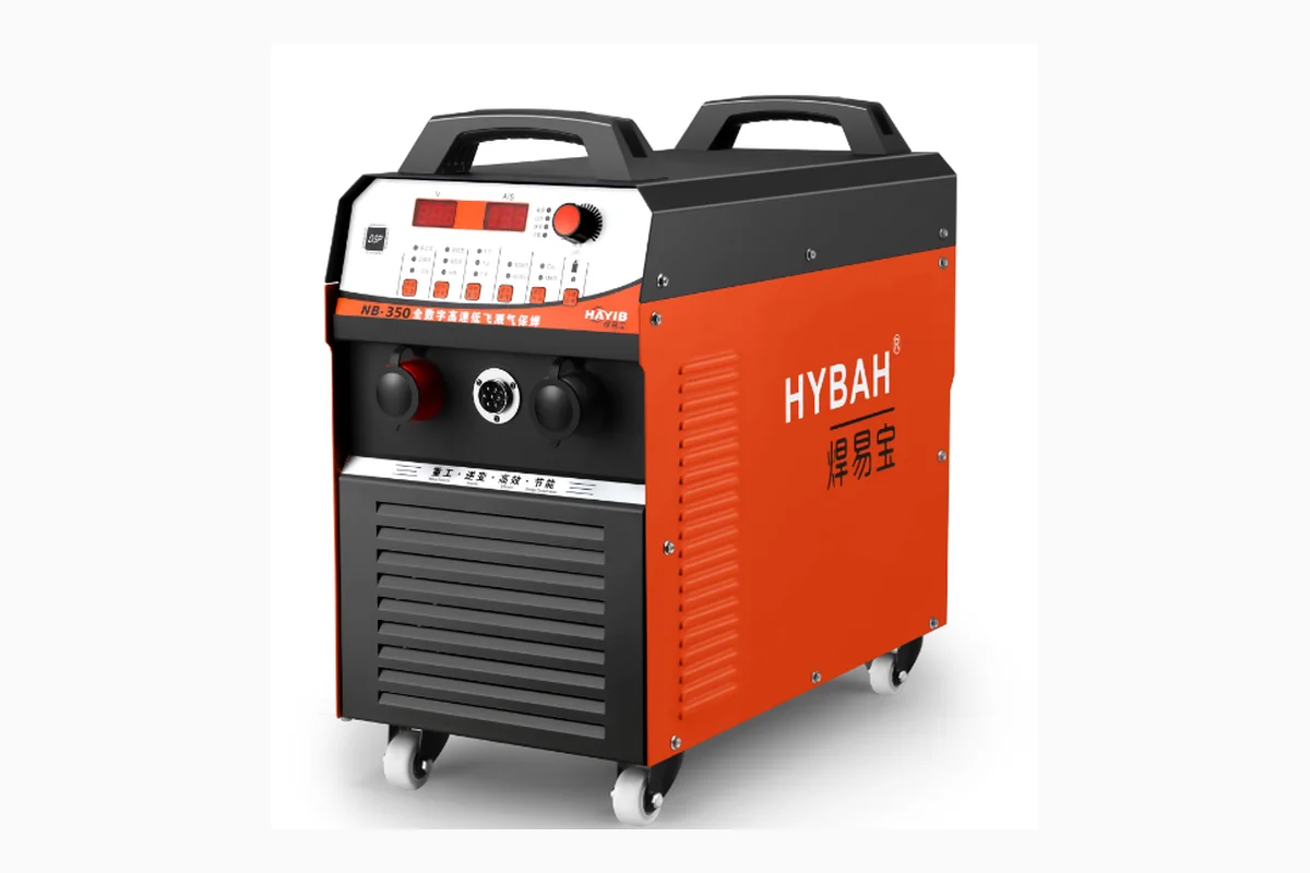
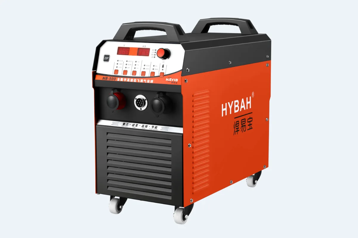
Welding stations should be at the end of the flow, away from cutting dust. The NB-350 and NB-500 MIG/CO2 welders are common choices for cage and coupler work. Provide fume extraction at each station — this is a safety requirement in most export markets and a worker retention issue everywhere.
Thread rolling with the HGS-40 is best placed next to welding, since threaded couplers often go straight into welded assemblies. The ZDTHJ-12 automatic spring making machine (12 mm) is a separate product line — keep it in its own zone if you run it alongside rebar work.
Safety Layout Essentials
- Minimum 1.5 m walkway between machine rows; 2.5 m where forklifts pass.
- Emergency stops on every machine must be reachable without stepping over material.
- Guard all shear and bending pinch points; CNC machines should have interlocked doors.
- Keep a 1 m clear zone around electrical panels for maintenance access.
- Mark crane swing zones on the floor and prohibit pedestrian crossing under loads.
Export and Certification Notes
Gongda equipment (Hefei, Anhui, China) ships to Russia, Spain, Latin America, the Middle East, Southeast Asia, and Africa. EAC certification is available for Russian and CIS markets — confirm this before ordering if you export finished rebar products into those regions.
For layout drawings, model selection, or capacity questions, contact the factory directly: WhatsApp +86 193 9277 7259 or email yuhua0095@gmail.com. A plant layout review before you pour foundations is cheaper than moving a 160-ton shear later.
Send your requirement on WhatsApp — we reply within one business day.
WhatsApp Request a Quote →More Articles
Single-Line vs Double-Line Rebar Machines: Which to Choose
Single-Line vs Double-Line Rebar Machines: Which to Choose If you are specifying a CNC rebar forming machine f…
Rebar Machine Electricity Requirements (380V, 50/60Hz)
Rebar Machine Electricity Requirements: 380V, 50/60Hz, and Generator Sizing for Remote Sites Most buyers sourc…
How to Calculate Rebar Processing Productivity
How to Calculate Rebar Processing Productivity: Bends Per Hour, Stirrups Per Shift, and Line Throughput Most b…
Rebar Machine Safety Operation Rules
Rebar Machine Safety Operation Rules: A Practical Guide for Buyers and Operators Rebar processing equipment is…
Rebar Machine Maintenance Checklist
Rebar Machine Maintenance Checklist: Daily, Weekly and Monthly Schedules That Prevent Downtime Every hour a CN…
CNC Stirrup Machine Cost and ROI Calculation
CNC Stirrup Machine Cost and ROI Calculation: What Buyers Should Actually Model When a fabrication shop or reb…
Ready to Talk Numbers?
Send us your rebar processing requirements and get a factory-direct quotation within one business day.